Tuesday 17 November 2015

Control your home using Android Voice Recognizer with Arduino

Home Controller :D

Sebarang pertanyaan/pembelian/bantuan boleh dm saya dia twitter eh:
twitter.com/zakimuslim_


I have a problem during uploading test run video on my blog. Feel free to watch on my FB!


Hardware:

-Arduino Board
-HC06 Bluetooth receiver
-Smartphone (Android)
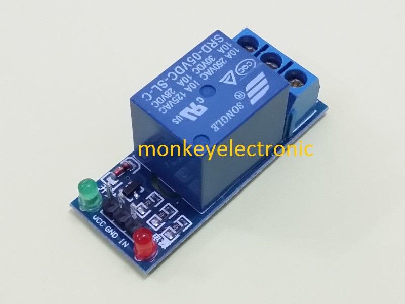
-Relay, 5VDC
   here types of relay that you can use. Relay the most important component in this simple project.
   Choose the right spec!

   5VDC / 10A / 240VAC


Relay module.


Circuit!

Some photos that can helps you :D
In my video i use "by pass" concept. So i can ON/OFF using switch and smartphone!


                                                     Connect bluetooth receiver like this!
                                        Vice versa, so Arduino & HC06 can communicate each other.
                                                           TX > RX, then RX > TX


Line that i've bold is 240VAC.
Beware, high voltage/current!


                            Sorry i can't draw the circuit in computer. Just by hand. Sucks!


Arduino Coding!

Directly Download Here


////////////////////////////////////////////////////////////////////////////////////////////////////////////////////////////////////////////


String incoming;

void setup()
{
  Serial.begin(9600);
  pinMode(8, OUTPUT);   //set pin 8,9 as output. where relays connected
  pinMode(9, OUTPUT);
}

void loop()
{
  if(Serial.available() > 0)
  {
    incoming = Serial.readString();   //check what your smartphone send to arduino
    if(incoming == "hi")     //<<<< change here. change words in quotes.   if you say "hi" to your smartphone pin 8,9 will turn HIGH
    {
      digitalWrite(8, 250);
      digitalWrite(9, 250);
      
    }
    else if(incoming == "goodbye")    //<<<< change here. change words in quotes.  if you say "goodbye" to your smartphone pin 8,9 will turn LOW
    {
      digitalWrite(8, LOW);
      digitalWrite(9, LOW);
    }

    else if(incoming == "daylight")   //<<<< change here. change words in quotes. if you say "daylight" to your smartphone pin 8 will turn LOW (turn lamp OFF)
    {
      digitalWrite(8, HIGH);
    }

    else if(incoming == "night")  //<<<< change here
    {
      digitalWrite(8, LOW);
    }

    else if(incoming == "hot")   //<<<< change here
    {
      digitalWrite(9, HIGH);
    }

    else if(incoming == "cool")  //<<<< change here
    {
      digitalWrite(9, LOW);
    }
  }
}


///////////////////////////////////////////////////////////////////////////////////////////////////////////////////////////////////////////////

Code Explaination.

String incoming;
-store text that your smartphone sends in string.

Serial.begin(9600);
-
Serial buadrate.

pinMode(8, OUTPUT);
-Set pin 8 on arduino board as output pin. where relays connected.

 if(Serial.available() > 0)
-Check if serial available or not.

incoming = Serial.readString();
-incoming is the words that you smartphone sends.

if(incoming == "hi") 
-check what words you've send from smartphone.

if(incoming == "hi")
    {
      digitalWrite(8, 250);
      digitalWrite(9, 250);
    }
-Check what you have send using your smartphone. If you send "hi" relay that connected on pin 8 and pin 9 will be triggered and lamp and fan will turn ON.


Smartphone Coding!

I use MIT APP INVENTOR to create this app. Its free, just create an account and start build own app here!
You also can import my code to edit in MIT APP INVENTOR.
Here link you can download my code and app that i've use in my video!


How to import .aia format to your appinventor IDE:


1. Click on "Projects"
2. Click on "import project (.aia) from my computer..."


3. After import the .aia file, you can see the app design in your appinventor IDE.
    Now you can change the design and label into your own language!


4. At the top right you can see the button "BLOCKS". Click it and you can see the code.


5. Once you finnished edit the app, you can click on "Build" to build the APK.


6. After that, copy the apk to your phone and install !!


How to use this app?

Turn on bluetooth on your smartphone.


Click on "Pilih Bluetooth" to connect your smart phone to the system.


Now select the bluetooth client. Click on HC06.


Click on "Sentuh" to start giving a command.


Your smartphone will print the text that he recognised on screen.


You also can send command by typing. Just tap on the textbox. Then click on "HANTAR" to send the command.


This app run on my Asus Zenfone 5 LTE  smoothly :D


DOWNLOAD LINK


File .aia; https://drive.google.com/file/d/0B3c_VPBO9Qq3M0FDQjRzang5bkk/view?usp=sharing 


Tuesday 29 September 2015

Create an EXE in Visual Basic 6.0 To Control Arduino Projects


Create an EXE Visual Basic 6.0 
To
 Control Arduino


Sebarang pertanyaan/pembelian/bantuan boleh dm saya dia twitter eh:
twitter.com/zakimuslim_

Theres have a little bit different between Visual Basic 6.0 and Visual Basic 2008. If you want to learn how to use serial communication and create an EXE in Visual Basic 6.0 here is video that i've make to help you in coding and how to find serial comm component in VB 6.0.

If you still dont have Visual Basic 6.0 software, you can download here for free!!
VB 6.0 Software:
https://drive.google.com/open?id=0B3c_VPBO9Qq3cHROTW5ydkVXOU0


How to find CD key!!


You need to watch on youtube because i've some problem during uploading this video on my blog :(
Tutorial Video!


VIDEO

VB 6.0 tutorial:
https://www.youtube.com/watch?v=uoyCcGM9nDA&feature=youtu.be


Arduino Code

You can copy and paste this code or directly download HERE ...
Modify this code if needed!


int led = 13;
String incoming;

void setup()
{
  Serial.begin(9600);
  pinMode(led, OUTPUT);
}

void loop()
{
  if(Serial.available() > 0)
  {
    incoming = Serial.readString();
    if(incoming == "Led ON")
    {
      digitalWrite(led, HIGH);
      Serial.println("LED is ON....");
    }
    else if(incoming == "Led OFF")
    {
      digitalWrite(led, HIGH);
      Serial.println("LED turning OFF.......");
    }
  }
}


Code Explaination

String incoming;
-string that vb send to arduino.

int led = 13;
-tell arduino i attach led on pin 13

Serial.begin(9600);
-Baud rate. Communication speed between Arduino and PC

pinMode(led, OUTPUT);
-set led as output

if(Serial.available() > 0)
-when serial is available. If Arduino read any byte

incoming = Serial.readString();
-read serial in string.

if(incoming == "TURN ON")
-if incoming string that arduino read is "TURN ON"

digitalWrite(led, HIGH);
-Arduino will turn on led on pin13


//////////////////////////////////////////////////////////////////////////////////////////////////////////////////////////////////////////////////


Visual Basic 2008


You also can learn how to use serial comm between Arduino and VB 2008 here. I also post my Arduino basic code to blink a LEDs using VB 2008.
VB 2008 tutorial:
http://ohhmyproject.blogspot.my/2015/09/control-arduino-using-visual-basic-2008.html 


Download Link

Arduino Code VB 6.0:
https://drive.google.com/open?id=0B3c_VPBO9Qq3VG0yY3hUbldScGc 


Visual Basic 6.0 software:
https://drive.google.com/open?id=0B3c_VPBO9Qq3cHROTW5ydkVXOU0

Sunday 27 September 2015

Control Arduino Using Visual Basic 2008


Visual Basic 2008 With Arduino

Sebarang pertanyaan/pembelian/bantuan boleh dm saya dia twitter eh:

i recommend watch this video on youtube for better quality
https://www.youtube.com/watch?v=OBJdnFVBfvY


Arduino Code


String incoming;
int led = 8;

void setup()
{
  Serial.begin(9600);
  pinMode(led, OUTPUT);
}

void loop()
{

  if(Serial.available() > 0)
  {
    incoming = Serial.readString();  //<<---this is the most important
    if(incoming == "TURN ON")
    {
      digitalWrite(led, HIGH);
    }
    else if(incoming == "TURN OFF")
    {
      digitalWrite(led, LOW);
    }
  }
}


Code Explaination

String incoming;
-string that vb send to arduino.

int led = 8;
-tell arduino i attach led on pin 8

Serial.begin(9600);
-Baud rate.

pinMode(led, OUTPUT);
-set led as output

if(Serial.available() > 0)
-when serial is available. If Arduino read any byte

incoming = Serial.readString();
-read serial in string.

if(incoming == "TURN ON")
-if incoming string that arduino read is "TURN ON"

digitalWrite(led, HIGH);
-Arduino will turn on led on pin8


Download link

Arduino Code:
VB 2008 Code:

Sunday 20 September 2015

Create Android Apps to Control Arduino

HOW TO CREATE ANDROID APP TO
CONTROL ARDUINO PROJECTS


In this tutorial i use:
-Arduino board
-HC06 Bluetooth Receiver
-LED
-Jumper cables

In this video i use Google Chrome browser to create the APK.
Before you start creating an application for android you need to go this website
http://appinventor.mit.edu/explore/

Click on the "Create apps!" at top  right.

Start Create App Now!


and log in with your gmail to create an account.
Then watch this video for the next step.

i recommend watch this video on youtube for better quality:


After you finished create and install the apps on your android, wire up HC06, LED, and Arduino like this.

Dont forget to connect 5V and Gnd pin from Arduino to breadboard!


Then copy and paste this Arduino Code and upload to your Arduino board!
Or you can directly download the code here  <<<<<<<<<<<<<<<<Download Code
Its very simple code. Modify the code if you want!


Remember! Disconnect jumper cables at TX and RX pin on Arduino board when you upload the code!


Now you ready test the code and apps together!


First turn on your device's bluetooth.Pair your device's bluetooth connection with HC06. If it request the pin number, the pin is 1234. Your need to do this for the first you connect your android and HC06


Second, open the apps that you have installed on your android, and
click on "Select Bluetooth Client"


Now you can see the bluetooth client named "HC06"


Click on it to connect with your Arduino board


 Now your android connected to your Arduino board,
You can see the "Connected To Arduino" on your screen


How your app? running smooth?
You can try this apps that i've make to control the blender. You can download the APK and Arduino code. Go to the bottom of this page and you can see "Download Link". Its work perfectly on my ASUS T00K.


Circuit...


HIGH VOLTAGE!

To handle high voltage/current you need a RELAY to seperate them. Arduino just can handle 5v voltage.
With relay you can separate high current and high voltage. This can avoid your Arduino from toasted!

You need a relay 5V 220V.
Its stand for 5V input,  220V output.
The coil of relay need 5vdc to switch from normally close state(NC)  to  normally open(NO) state.


this type of relay that you can use:


In my case, i use this relay. It can triggered at 5vdc but need 9vdc power supply.
i bought this at Kytron, Seksyen15, Shah Alam, Malaysia.


Your circuit become easier if youre using relay module.

http://www.lelong.com.my/srd-5v-dc-5-pin-relay-mcs123-167817400-2016-09-Sale-P.htm


Here my another simple projects that i've use MIT Inventor and HC06 Bluetooth Receiver.
I will make a tutorial for this project later :D


Another project. Tutorial already posted on my blog


Download Link

Arduino Code:

-LED Controller


Saturday 19 September 2015

Arduino + Robotis

Playing with 

Arduino + Robotis Parts

Sebarang pertanyaan/pembelian/bantuan boleh dm saya dia twitter eh:
twitter.com/zakimuslim_

i recommend watch this video on youtube for better quality:
https://www.youtube.com/watch?v=xmYYOmiEVDI


       Security Gates

In this post i just use serial monitor and keyboard.

This is really simple tutorial. Its take around 30minutes.
In this tutorial, i use:
 -Arduino Mega 2560                                
 -Robotis Play600 parts.
 -Motor Driver L293D
 -Red and Green LED.
 -Breadboard
 -Jumper Cables


Actually Robotis Play600 Pets looks so boring, then i just wanna make it become more interesting by using Arduino. I think this robotis play600 cheaper than other robotis model. I dont know how much because i got this for free. I got this during lucky draw Fira Roboworld Cup. I'm so lucky.  So i make this during my weekend......


1. Open the body and solder two female jumper cables at the battery casing.

     Like this!

    -Unscrew the screw and open this part


               -Solder the jumper cables to DC motor cables(at battery casing). I do this because i want to
                drive the DC motor inside using a motor driver.
                Maybe this image can help you to understand what i mean :)


After finish, assemble and screw them up!


2. Wiring between Arduino, Motor Driver, and Robotis

Connect the wiring like this.
In my video i use only 5V power supply to power up the motor. I'm not using any battery, i use from Arduino 5V pin.
Make sure your circuit is correct.

Dont forget to include the Green and Red LED in the circuit!


3. Assemble your Robotis Parts

  
 -Assemble them as creative as creative can.

                                                                      this is mine.


4. Arduino Code

Once you've finished, now you ready to upload the code!
This is my code. You can copy and paste or directly download here .


String password_input;
String pass = "zaki";
int gateup = 7;
int gatedown = 8;
int stopp = 9;
int go = 10;

void setup()
{
  Serial.begin(9600);     //baud rate
  pinMode(gateup, OUTPUT);     //pin for gate up
  pinMode(gatedown, OUTPUT);   //pin for gate going down
  pinMode(stopp, OUTPUT);      //red led pin
  pinMode(go, OUTPUT);         //green led
  Serial.println("Enter Password");
}
void loop()
{
  digitalWrite(stopp, HIGH);
  if (Serial.available() > 0)
  {
    password_input = Serial.readString();  //password key in by user
    if (password_input == pass)            //if password is correct
    {
      digitalWrite(stopp, LOW);           //red led OFF
      delay(500);
      digitalWrite(go, HIGH);             //green led is high
      Serial.print("Password Received: "); //print on serial monitor
      Serial.println(password_input);
      delay(500);
      analogWrite(gateup, 180);           //open the gate
      Serial.println("Gate Open");
      delay(2500);
      digitalWrite(gateup, LOW);         //gate open for 2 seconds
      Serial.println("delay 2 seconds......");
      delay(1500);
      digitalWrite(go, LOW);  //green led OFF
      delay(500);
      digitalWrite(stopp, HIGH);  //red led high
      delay(500);
      Serial.println("Gate Closed!");
      analogWrite(gatedown, 150);     //close the gate until get the correct password
      delay(650);
      digitalWrite(gatedown, LOW);
      delay(500);
      Serial.println("Please Enter Password"); //ask user to key in the password again
    }
    else 
    {
      Serial.print("Password Received: ");     //if the password is invalid
      Serial.println(password_input);
      Serial.println("Invalid Password!");
      Serial.println("Please enter the password again");
    }
  }
}


Code Explaination


String password_input;
-this string use for storing the password that user key in

String pass = "zaki";
-this string is the password. User need to key in "zaki" at serial monitor to open the gate.
-you can change the password with modify this string like this:
String pass = "the password you want";
example:
String pass = "vnsicxx34kjx";

int gateup = 7;
-pin on arduino that i use to open the gate.

int gatedown = 8;
-pin on arduino that i use to close the gate.

int stopp = 9;
-pin on arduino that i use to Red LED.

int go = 10;
-pin on arduino that i use to Green LED.

Serial.begin(9600);    
-baud rate

pinMode(gateup, OUTPUT);
-Set pin gateup as output

pinMode(gatedown, OUTPUT);
-Set pin gatedown as output

pinMode(stopp, OUTPUT);
-set red led pin as output

pinMode(go, OUTPUT);
-set green led pin as output

Serial.println("Enter Password");
-ask user to enter the password on serial monitor

digitalWrite(stopp, HIGH);
-Red LED always ON because gate always close

if (Serial.available() > 0)
-If serial communication with Arduino is available(check), all code ready to execute. If not, code
  never to execute

password_input = Serial.readString();
-read the password that key in by user in string

if (password_input == pass)
{
      digitalWrite(stopp, LOW);           //red led OFF
      delay(500);
      digitalWrite(go, HIGH);             //green led is high
      Serial.print("Password Received: "); //print on serial monitor
      Serial.println(password_input);
      delay(500);
      analogWrite(gateup, 180);           //open the gate
      Serial.println("Gate Open");
      delay(2500);
      digitalWrite(gateup, LOW);         //gate open for 2 seconds
      Serial.println("delay 2 seconds......");
      delay(1500);
      digitalWrite(go, LOW);  //green led OFF
      delay(500);
      digitalWrite(stopp, HIGH);  //red led high
      delay(500);
      Serial.println("Gate Closed!");
      analogWrite(gatedown, 150);     //close the gate until get the correct password
      delay(650);
      digitalWrite(gatedown, LOW);
      delay(500);
      Serial.println("Please Enter Password"); //ask user to key in the password again
    }

-All of this code will be execute if the user enter the correct password


else 
    {
      Serial.print("Password Received: ");     //if the password is invalid
      Serial.println(password_input);
      Serial.println("Invalid Password!");
      Serial.println("Please enter the password again");
    }

-this code will be executed if user enter the incorrect password
-print "Invalid Password" and "Please enter the password again"


If you have any problem with wiring, you can refer my older post about L293D and Blink More Than 1 LEDs 

or directly pm me on
twitter @zakimuslim_ 
facebook Mohammad Zaki 


Download Link

Wednesday 16 September 2015

Arduino + 7 Segment

Arduino + 7 Segment

Sebarang pertanyaan/pembelian/bantuan boleh dm saya dia twitter eh:

In this post i use :
-Arduino Mega 2560
-5101AS 7 segment
-Breadboard
-Jumper cables.


5101AS 7 segment


Okay before we start wire up the 7 segment, we should know which one pin is "common" pin.

In my case, i use 5101AS model. So when i check the datasheet, i get this....

Common(com) is at the middle. Labelled as "com".

okay now lets go the next step..


wire up your component like this.
remember! dot always at the downside


After finished, open your Arduino IDE and copy and paste this code or just download it here


void setup() {
  pinMode(2, OUTPUT);   //set all pin that i've use as output pin
  pinMode(3, OUTPUT);
  pinMode(4, OUTPUT);
  pinMode(5, OUTPUT);
  pinMode(6, OUTPUT);
  pinMode(7, OUTPUT);
  pinMode(8, OUTPUT);
  pinMode(9, OUTPUT);
  
}

void loop() {
  one();               //tunjuk nombor 1
  delay(1000);    //display number 1 for 1000miliseconds(1second)
  two();
  delay(1000);
  three();
  delay(1000);
  four();              //display number 4
  delay(1000);    //display number 4 for 1second
  five();
  delay(1000);
  six();
  delay(1000);
  seven();
  delay(1000);
  eight();            //keluar nombor 8
  delay(1000);   //akan keluar nombor 8 selama 1 saat
  nine();
  delay(1000);

}


/* modify code here to display another number or characters*/

void one(void)                 //<------------void to display number 1
{
  digitalWrite(2, LOW);      //centre
  digitalWrite(3, HIGH);     //top left
  digitalWrite(4, LOW);      //top
  digitalWrite(5, LOW);      //top right
  digitalWrite(6, HIGH);     //bottom left
  digitalWrite(7, LOW);      //bottom
  digitalWrite(8, LOW);      //bottom right
  digitalWrite(9, HIGH);     //dot
}


void two(void)          //<---------------- void to display number 2
{
  digitalWrite(2, HIGH);      //centre
  digitalWrite(3, LOW);     //top left
  digitalWrite(4, HIGH);      //top
  digitalWrite(5, HIGH);      //top right
  digitalWrite(6, HIGH);     //bottom left
  digitalWrite(7, HIGH);      //bottom
  digitalWrite(8, LOW);      //bottom right
  digitalWrite(9, HIGH);     //dot
}


void three(void)    //<------- call this void to dsplay number 3
{
  digitalWrite(2, HIGH);      //centre
  digitalWrite(3, LOW);     //top left
  digitalWrite(4, HIGH);      //top
  digitalWrite(5, HIGH);      //top right
  digitalWrite(6, LOW);     //bottom left
  digitalWrite(7, HIGH);      //bottom
  digitalWrite(8, HIGH);      //bottom right
  digitalWrite(9, HIGH);     //dot
}


void four(void)      //<----diguna kan untuk keluar kan nombor 4. 
{
  digitalWrite(2, HIGH);      //centre
  digitalWrite(3, HIGH);     //top left
  digitalWrite(4, LOW);      //top
  digitalWrite(5, HIGH);      //top right
  digitalWrite(6, LOW);     //bottom left
  digitalWrite(7, LOW);      //bottom
  digitalWrite(8, HIGH);      //bottom right
  digitalWrite(9, HIGH);     //dot
}


void five(void)
{
  digitalWrite(2, HIGH);      //centre
  digitalWrite(3, HIGH);     //top left
  digitalWrite(4, HIGH);      //top
  digitalWrite(5, LOW);      //top right
  digitalWrite(6, LOW);     //bottom left
  digitalWrite(7, HIGH);      //bottom
  digitalWrite(8, HIGH);      //bottom right
  digitalWrite(9, HIGH);     //dot
}


void six(void)
{
  digitalWrite(2, HIGH);      //centre
  digitalWrite(3, HIGH);     //top left
  digitalWrite(4, HIGH);      //top
  digitalWrite(5, LOW);      //top right
  digitalWrite(6, HIGH);     //bottom left
  digitalWrite(7, HIGH);      //bottom
  digitalWrite(8, HIGH);      //bottom right
  digitalWrite(9, HIGH);     //dot
}


void seven(void)
{
  digitalWrite(2, LOW);      //centre
  digitalWrite(3, LOW);     //top left
  digitalWrite(4, HIGH);      //top
  digitalWrite(5, HIGH);      //top right
  digitalWrite(6, LOW);     //bottom left
  digitalWrite(7, LOW);      //bottom
  digitalWrite(8, HIGH);      //bottom right
  digitalWrite(9, HIGH);     //dot
}


void eight(void)
{
  digitalWrite(2, HIGH);      //centre
  digitalWrite(3, HIGH);     //top left
  digitalWrite(4, HIGH);      //top
  digitalWrite(5, HIGH);      //top right
  digitalWrite(6, HIGH);     //bottom left
  digitalWrite(7, HIGH);      //bottom
  digitalWrite(8, HIGH);      //bottom right
  digitalWrite(9, HIGH);     //dot
}


void nine(void)
{
  digitalWrite(2, HIGH);      //centre
  digitalWrite(3, HIGH);     //top left
  digitalWrite(4, HIGH);      //top
  digitalWrite(5, HIGH);      //top right
  digitalWrite(6, LOW);     //bottom left
  digitalWrite(7, HIGH);      //bottom
  digitalWrite(8, HIGH);      //bottom right
  digitalWrite(9, HIGH);     //dot
}


Code explaination


  pinMode(2, OUTPUT);   
- to set all pin that i've use as output pin

one();
-called void "one" to display number 1 on 7 segment.

five();
-called void "five" to display number 5 on 7 segment.

delay(1000);
-to display the number on 7 segment for 1 second

void one(void) 
{
  digitalWrite(2, LOW);      //centre
  digitalWrite(3, HIGH);     //top left
  digitalWrite(4, LOW);      //top
  digitalWrite(5, LOW);      //top right
  digitalWrite(6, HIGH);     //bottom left
  digitalWrite(7, LOW);      //bottom
  digitalWrite(8, LOW);      //bottom right
  digitalWrite(9, HIGH);     //dot
}
-this is void wheres i use it to create the number


for example;

digitalWrite(8, HIGH);      //bottom right

-on 7 segment will show this


Download Link

Arduino Code:
https://drive.google.com/open?id=0B3c_VPBO9Qq3aUNnMXVIbEc3N3M